Rendering techniques
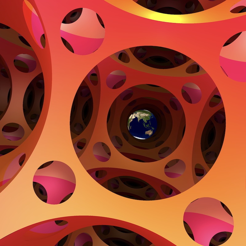
Rendering non-euclidean geometry
From the computer screen to the ambient space
Our work is based on Fermat’s principle: the light follows paths which locally minimizesthe distance between two points (also known as geodesics). Unlike in the euclidean space $\mathbb E^3$, the geodesics are usually not “straight” lines, which affects our perception of the ambient world.
The main strategy to produce images is the following. Imagine that the observer is located at a point $o$ in the space $X$. We interpret the computer screen as a vertical affine plane in the tangent space $T_oX$. Hence, every pixel on the screen defines a direction, represented by a vector $u$ in $T_oX$. For such a vector, we consider the geodesic $\gamma$ of $X$ starting at $o$ and directed by $u$. We compute the first intersection of $\gamma$ with an object in the scene (by doing so we follow the light rays in the reversed direction).
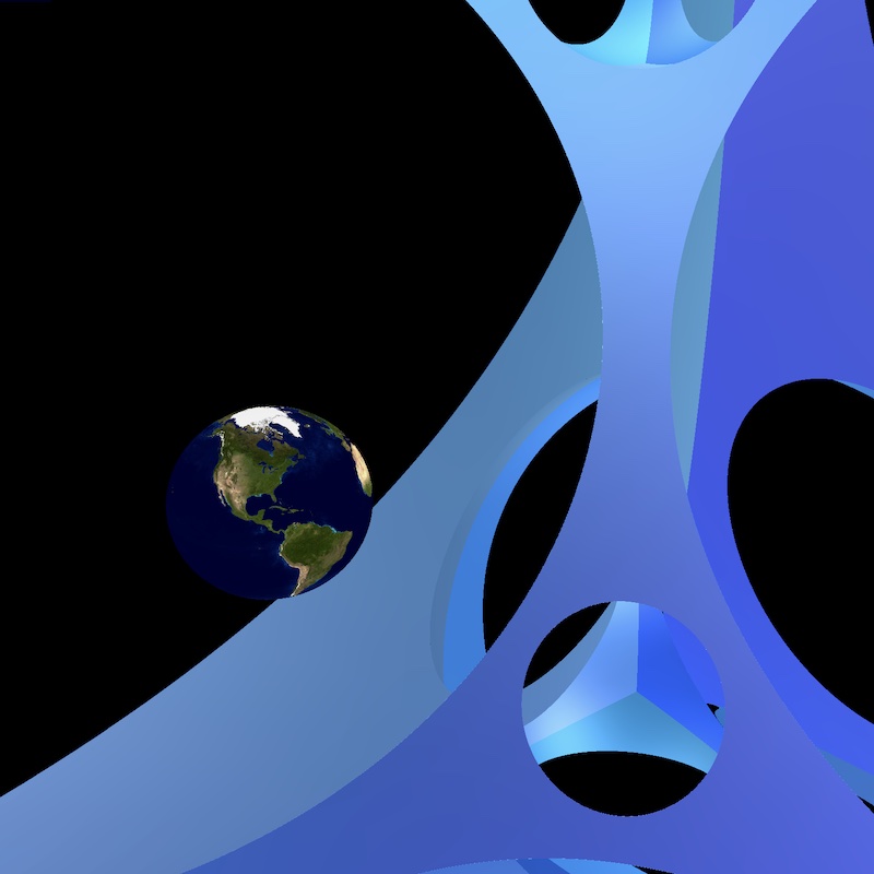
- If such an object exists, then we color the corresponding pixel on the screen with the color of the object.
- If $\gamma$ does not intersect any object, we leave the pixel black.
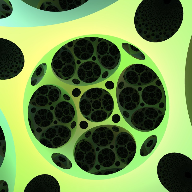
Raymarching
The difficulty in this program is to compute the intersection of $\gamma$ with objects in the scene. Indeed, for some geometries, the geodesics may have a rather complicated forms, which makes explicit computations impossible. To bypass this difficulty we use a strategy called raymarching.
Each object is not represented by a mesh (i.e. a triangulation) but by a signed distance function $\sigma \colon X \to \mathbb R$. For each point $p \in X$ in the space, the quantity $\sigma(p)$ represents the distance to the boundary of the object. It is counted positively (respectively negatively) if $p$ is outside (respectively inside) the object. The algorithm now works as follows. Starting with a point $p_0$ and a direction $u$ at $p_0$, we use the signed distance functions to determine the distance from $p_0$ to the closest object in the scene, say $d_0$. Then we follow the geodesic $\gamma$ starting at $p_0$ and directed by $u$ along a length $d_0$, and reach a point $p_1$. We now repeat the process: the signed distance functions tell us at which distance is the closest object from $p_1$, say $d_1$, and we follow the geodesic $\gamma$ along a distance $d_1$, etc. When the distance to the closest object passes an arbitrary small threshold, we stop the process and decide that the geodesic ray has hit the object.
In practice, we do not need the exact signed distance function of an object. A suitable under-estimator is enough. We can refine also the algorithm using directed signed distance functions. More details can be found in this article.
Virtual reality
Stereographic vision is based on the following phenomenon. As they do not have the same position, the left and right eyes do not see the exact same picture. These parallax differences can be interpreted by our brain to give depth cues. A virtual reality headset has a separate screen for each eye. In the VR mode of our software, we have set up two cameras in the scene, separated by the interpupillary distance, recording the images for the left and right eyes. This works reasonably in many situations, especially if the objects in the scene are close to us. Indeed, at a small scale, the geometry can be thought of as a “small” deformation of the euclidean space, and our brain is still able to merge the two pictures. However, for objets which are far away the curvature of the space may have a strong influence. The left image and right images become so different that our brain get lost.
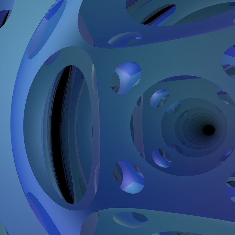
Path tracer
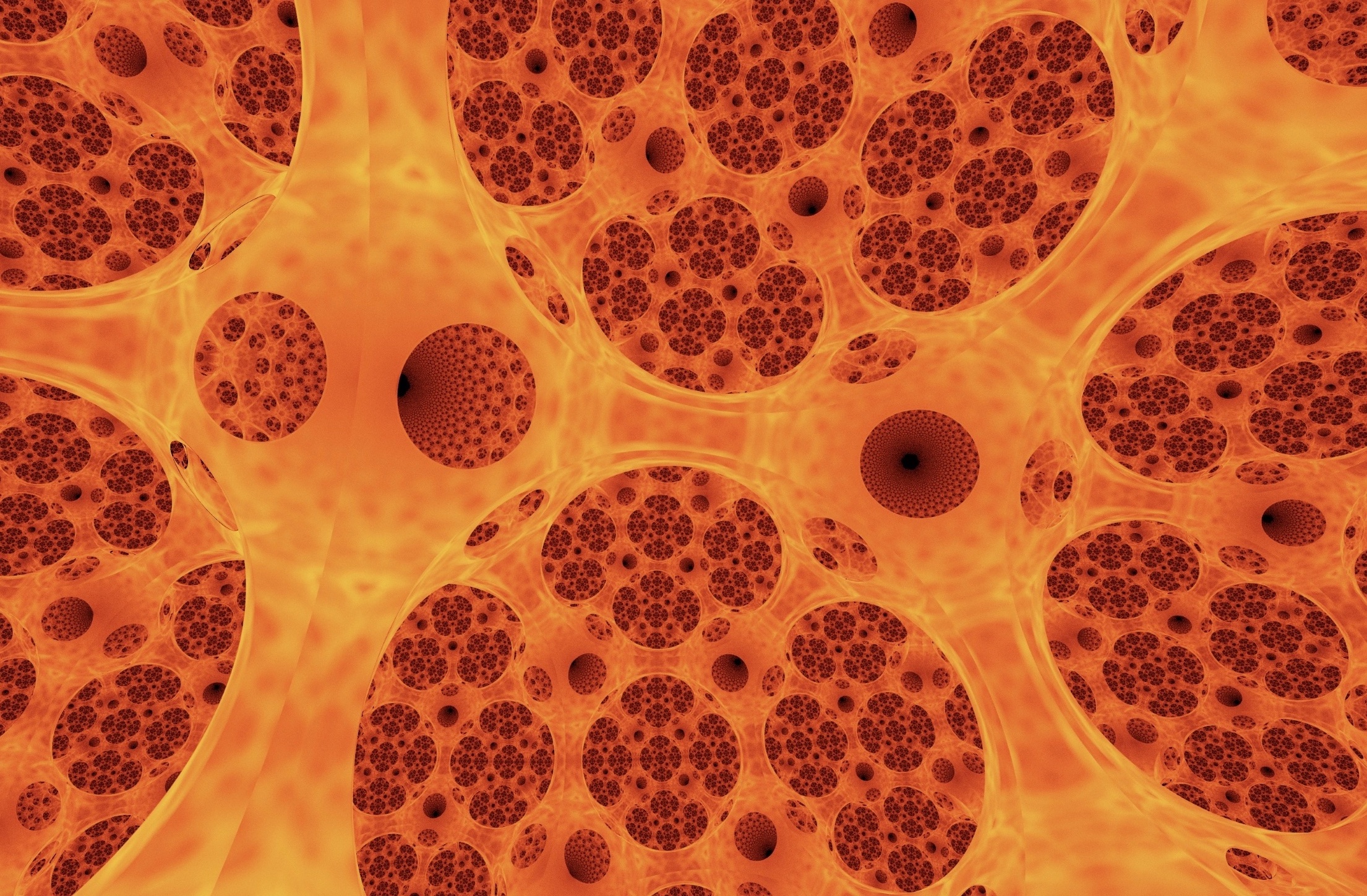
Hyperbolic Fire
Path traced view of hyperbolic tiling, rendered as hot glass
The default mode of our software uses the empiric Phong model to render the shading of an object. Phong justified his model, by comparing a render with a real-life photograph of a (euclidean) scene. We use this model far outside the setting in which it was designed for, so one could question whether or not it produces accurate results in our non-euclidean spaces. To address this issue we developed a path tracing mode in our software. The idea is the following. Numerous light rays are thrown from our eye in the scene. Each time the ray hit an object, it bounces (with some random perturbation), loosing some energy, until it reach a light source. This technique does not work in real time anymore. However, it captures many optical effects such as diffusion, reflections, refractions, soft shadows, etc. You can look at the gallery to see some images produced in this way.